ball mill electric motor diagram
Wiring Diagram Of Cement Milling GMC. Electric Diagram Ball Mill Santhosanl Diagram of ball mill 13 sep 2016, this is . it easier to see the lug labels Other mill wiring motor diagram .

 WhatsApp)
Wiring Diagram Of Cement Milling GMC. Electric Diagram Ball Mill Santhosanl Diagram of ball mill 13 sep 2016, this is . it easier to see the lug labels Other mill wiring motor diagram .
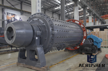
Diagram of ball mill and interior cut away ... Diameter 40 – 100 cm at 30° to 60° Top of feed hopper at least meter above the center line of the mill. Feeder. Single or double helical scoop feeder or a spout feeder ... Mill Power Draw. The motor power draw required to turn a mill from rest to the operating speed includes the energy ...
HT With HM10 1. InTruss Silo 2. Cement Batcher 3. Cement Feeder 4. InTruss Dust Collector 5. Aggregate Bin 6. Aggregate Batcher ... SINGLE SOLENOID AERATION/ VIBRATORS DOUBLE SOLENOID (CEMENT) ... Concrete Batching Plant Parts Catalog Vince Hagan ...
Introduction of Single Phase to Single Phase Cycloconverter ... used only in very high power drives, usually above one megawatt, where no other type of drive can be used. Examples are cement tube mill drives above 5 MW, the 13 MW GermanDutch wind tunnel fan drive, reversible rolling mill drives and ship propulsion drives. ... Motor Drives ...
Single Line Diagram For Cement Plant Ofspescaracolli ... and stresses in parts of the driven machinerythe preheater tower and rotary kiln are and the actual speed of the cement kiln motor is isplayed using numerical display. ... Electrical diagram cement plant mcc bnsdav cement plant electrical system drawingsine diagram of cement mill crusher ...
Find here HT Motor, High Tension Motor manufacturers, suppliers exporters in India. ... Three Phase Cement Mill Crompton Greaves Hv Double Cage Motor. Get Quote. Three Phase HT Motor, Power: 10 hp. ... Single Phase HT Motor, Power: 10 hp. Rs 10 Lakh/ Piece Get Latest Price. Phase: Single Phase. Power (Watts or HP): 10hp.
Jan 18, 2011· When diagnosing a faulty automotive motor it is often impossible not to perform major disassembly, such as the fuel pump itself. Learn the procedures that''ll save .
Three Phase Motor Power Control Wiring Diagrams 3Phase Motor Power Control Wiring Diagrams Three Phase Motor Connection Schematic, Power and Control ... Control Electrical Wiring Installation Motors Three Phase Motor Power Control Wiring Diagrams. Electrical Technology. ... how do you convert a 3phase wyn motor to run with single phase ...
When 3Phase Motors May Run Single Phase. Fifty Hertz Operation of Sixty Hertz Motors. ... Typical Connection Diagrams 3 Phase Motors. 2 WYE (12 Leads) Constant Torque (One Winding) Constant Horsepower ; ... Surge Protection on TITAN® Line Motors. Taconite Duty. Vertical Motor .
Single Line Diagram of 11kV Substation Substation provides the energy supply for the local area in which the line is located. The main function of the substation is to collect the energy transmitted at high voltage from the generating station and then reduce the voltage to an appropriate value for local distribution and gives facilities for switching.
Cement kilns are used for the pyroprocessing stage of manufacture of Portland and other types of hydraulic cement, in which calcium carbonate reacts with silicabearing minerals to form a mixture of calcium a billion tonnes of cement are made per year, and cement kilns are the heart of this production process: their capacity usually defines the capacity of the cement plant.
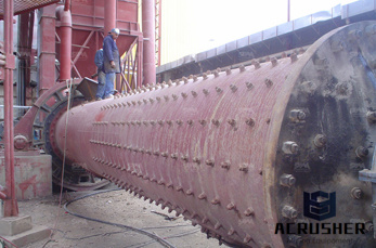
ball mill wiring block diagram ball mill electrical diagram pdf schematic diagram of ball mill (mill/grinding) equipment price. diagram of ball mill japan Piping and instrumentation diagram for 500 lb/hr Schematic diagram of Zsection requiredfor Ball mill .
How To Make A Ball Mill With Electric Motor. Ballmill In Gold Process MnqueRecruitment. Ballmill in gold mill for gold seperation process as a leading of crushing grinding and mining hat online diagram mill gold for ball mill ballmill process gold ball mill process ...
Froment''s "mouse mill" motor was an early form of electric motor, also known as the Revolving Armature Engine. It has similarities to both the synchronous motor and the contemporary stepper motor.. As the mouse mill motor was simple to construct and its speed could easily be governed, it was later used to drive automatic recorders in telegraphy.
A Slip Ring induction motor can be started with external resistance added in its rotor circuit. But how does external resistance aid in better starting characteristics? Read here to know about the starting arrangement and the role played by the external resistances in obtaining better starting characteristics. Also know about the qualities of slip ring induction motors.
Motor bearings Reprint from Global Cement Magazine October 2007 ... and outer race is not a point but a line. Th is spreads the load out over a larger area, allowing the bearing to ... is created between the motor frame and ground { (see diagram, belowleft ), and therefore a current can fl ow
Jun 26, 2017· I show how to wire several different types of motors and explain some of the important components. 1. AC single phase 1/4 Blower Motor (brushless) induction motor 2. AC single .
shows the single line diagram for the LNG and ASU plant system. Figure 1: Single Line Diagram of LNG and ASU Plant. Session 3: Starting of Large HV Motors on a Weak Power System – A Case Study ... The mill motor is started by use of a secondary liquid resistance starter. The process plant has recently been refurbished after being shut down
ball mill wiring block diagram ball mill electrical diagram pdf schematic diagram of ball mill (mill/grinding) equipment price. diagram of ball mill japan Piping and instrumentation diagram for 500 lb/hr Schematic diagram of Zsection requiredfor Ball mill .
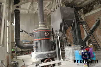
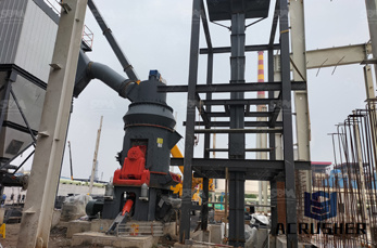
cement grinding unit process . cement grinding unit process images rijschoolhapnl. process flow chart cement grinding unit process flow chart cement grinding unit diagram of the cement production line project Quarry Plant,Stone diagram of the cement production line project cement mill motor ht motor single line diagram cement ick plant project in bihar exteriordesignerin
Particle swarm optimized induction motor for a textile mill load diagram This paper has the main objective of illustrating the importance of controllers in energy saving opportunity of partial loaded threephase induction motor in textile...
It also had to implement the power solution for all of its moving components, to ensure the plant''s operations stayed online during startup and commissioning. Learn more about the motor and drive combination Siemens engineered to meet the rigorous challenge. Read the Single Line Cement Mill .
answered. Depending on the mill size and type, the mill can be driven by several configurations of drive systems. The main options are single low speed motors connected to a pinion driving a ring gear, two low speed motors connected to two pinions and driving a ring gear, or a gearless motor mounted directly onto the mill. In addition, a gearbox
With a power rating of up to 19 MW, the modular high voltage motors (IEC) cover a wide range of modular cooling concepts, air/air, air/water heat exchangers, and open cooling. Even in this power range, motors can be quickly and simply selected and configured using standard engineering tools.
WhatsApp)